Shreethan Palla · March 2023
Rubik’s Cube Solving Robot
A six-axis Rubik’s Cube-solving robot I built in seventh grade.
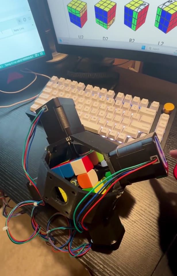
I salvaged the stepper motors from my old 3D printer and built around the hardware I had. Five frame iterations and repeated code and motion tuning took the project from individual motor tests to a first solve.
Build story
Getting a stepper motor moving
I took apart my old 3D printer to salvage its stepper motors. I started by getting one motor working, using the hardware I already had rather than buying a new set.
Single-axis testing
I tested one axis before moving on to coordinated motion. These tests let me work on individual turns before adding the complexity of the full mechanism.
Five frame iterations
I went through five frame designs to balance easy cube loading with a rigid mechanism.
The issueThe cube needed to go in and out without taking the whole robot apart, but the frame also had to hold it securely while the motors applied torque.
What changedI settled on a magnetic design that could come apart conveniently while staying sturdy enough to hold the cube during turns.
What I learnedEase of assembly and mechanical stiffness had to be designed together. The useful design was a compromise between the two.
When the wiring became the problem
Intermittent connections made troubleshooting much harder than it needed to be.
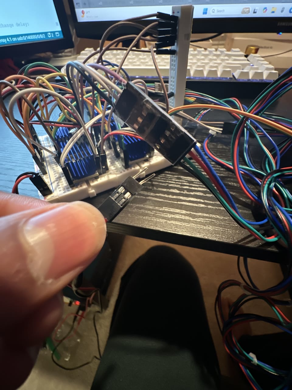
The issueCables would randomly stop working. An unreliable connection could make the same setup behave differently from one test to the next.
What I learnedReliable connections are part of the design, not just a detail to finish later. This experience inspired me to start designing my own PCBs.
Two axes, with all six connected
I moved on to testing two axes with the full six-axis setup connected.
Testing all six axes
Testing all six axes brought the mechanism together, but getting every cube face to line up reliably was a much bigger challenge than getting one motor to turn.
Skipped steps and misaligned faces
Face alignment was one of the biggest problems in the build.
The issueMotors skipped steps, microstepping was not behaving as expected, and the frame was not secure enough. I traced the problems to incorrect stepper-driver settings, insufficient torque and frame movement.
What changedI refined the frame and optimized the motor-control code, with repeated tuning and testing to keep the commanded step counts consistent.
What I learnedA command to turn is not a guarantee that the face reaches the right position. Electrical settings, available torque and mechanical rigidity have to work together.
The first solve
Reaching a first solve was the milestone that brought the motor tests, wiring and mechanism together. It also gave me a clearer view of what still needed to become more reliable.
Looking back and ahead
What I made
I designed and iterated the magnetic frame five times, tuned the motor-control code and tested the robot using motors salvaged from my old 3D printer.
What I learned
I learned to troubleshoot wiring, motor control and mechanical rigidity as one system. Consistent commanded steps are useful, but they do not measure the actual shaft position or guarantee that no steps were missed.
What inspired me
The frustration of intermittent cable connections pushed me toward designing my own PCBs for future projects.
What’s next
I would keep the convenient magnetic loading design, build a more secure frame and add motor-position feedback, such as encoders, so I could check shaft position rather than relying only on commanded steps.